Metal components rarely fail without warning. A hairline crack near a weld, reddish staining beneath paint, or a loose fastener can reveal months of hidden damage. Engineers investigate these clues through failure analysis, material testing, dimensional checks, and maintenance records. The goal is not merely replacing a broken part. It is understanding why the part failed.
Corrosion scientist Herbert H. Uhlig described corrosion as “the destructive attack of a metal by chemical or electrochemical reaction with its environment.” This principle remains highly relevant in factories, vehicles, bridges, and marine equipment. Moisture, salt, heat, vibration, poor drainage, and incompatible metals can act together. Even a strong alloy may deteriorate quickly when its environment is misunderstood.
So, how to improve durability of metal components? Start with the real service conditions. Select materials for load, temperature, chemicals, and expected contact. Control welding quality and reduce sharp corners that concentrate stress. Apply suitable coatings, seal exposed joints, and design paths for water to escape. Scheduled inspections should check thickness loss, cracking, distortion, and fastener looseness. Small defects are cheaper to repair.
No checklist is perfect. A coating may look intact while corrosion advances underneath. A polished surface may hide fatigue damage. Engineers must question assumptions and compare laboratory results with field evidence. Standards, traceable test methods, and documented maintenance improve reliability. Durability is therefore a design decision, a manufacturing discipline, and an ongoing responsibility—not a feature added after failure.
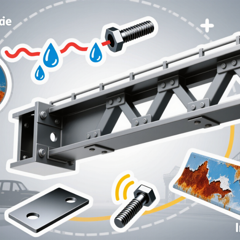
Metal components rarely fail from one cause. More often, several small weaknesses interact over time. Corrosion is a common starting point, especially where water collects under coatings, seals, or fastener heads. Pitting can look minor. Yet each pit creates a sharp stress concentration. Salt, humidity, and chemical exposure accelerate this damage. Dissimilar metals can also create galvanic corrosion when moisture connects them.
Repeated loading causes fatigue, even when each load remains below the stated strength. Cracks may begin around holes, weld toes, threads, or sharp corners. They grow quietly with every vibration cycle. Overloading produces faster deformation, bending, or sudden fracture. Excessive wear removes protective material from sliding surfaces. Poor alignment makes it worse. Heat can reduce hardness, distort dimensions, or weaken heat-treated parts. Manufacturing defects matter too. Inclusions, voids, and improper machining may remain hidden until service demands increase.
Durability improves when inspections match the real operating environment. Check for rust stains, loose joints, unusual noise, surface scoring, and small changes in shape. Measure critical dimensions instead of relying only on appearance. Clean and dry joints regularly, then repair damaged coatings before corrosion spreads. Use suitable materials, controlled tightening, generous radii, and drainage paths during design. Maintenance records should include loads, temperature, moisture, and failure locations. A checklist helps, but it is not enough. Engineers can misread early damage, especially when a component still looks strong. That uncomfortable possibility deserves attention.
Metal components rarely fail from one cause. In field inspections, cracks often begin at threads, sharp corners, or weld toes. These areas concentrate stress. A small load can become severe locally. Repeated loading then creates microscopic cracks. This process is fatigue. It may continue silently for months. Vibration, bending, and sudden impact accelerate crack growth. The final fracture can appear unexpected, although damage started much earlier.
Corrosion weakens metal in a different but connected way. Moisture, salts, chemicals, and trapped dirt attack exposed surfaces. Pits are especially dangerous. Their narrow shapes increase local stress. A corroded pit can become a fatigue initiation point. I have seen components with acceptable average thickness fail near one deep pit. That finding is easy to underestimate. Visual checks alone may miss subsurface damage. Thickness measurements, dye penetrant testing, and scheduled torque checks provide stronger evidence. Inspection methods must match the component and its service conditions.
Durability improves when design and maintenance address the actual damage mechanism. Use generous fillets, smooth transitions, and suitable materials. Reduce vibration before it reaches the joint. Keep water from collecting around fasteners and welds. Protective coatings help, but damaged coatings need prompt repair. They are not permanent solutions. Control loads, clean deposits, and record inspection findings consistently. Review failures without blaming operators too quickly. Sometimes the maintenance schedule is wrong. Sometimes the design leaves no margin for real-world abuse. That uncomfortable distinction can prevent another failure.
| Failure Mechanism | Typical Cause or Loading Condition | Relevant Engineering Indicator | Common Damage Pattern | Recommended Improvement | Verification Method |
|---|---|---|---|---|---|
| Static Overload | A single force, pressure, impact, or torque exceeds the component's load capacity. | Applied stress approaches or exceeds yield strength; fracture may occur when tensile stress reaches ultimate strength. | Permanent deformation, local yielding, buckling, or sudden ductile/brittle fracture. | Increase section thickness, reduce stress concentrations, select a suitable material, and apply an appropriate safety factor. | Tensile, compression, bending, torsion, and proof-load testing in accordance with the design requirement. |
| Stress Concentration | Sharp corners, keyways, holes, threads, weld toes, grooves, or abrupt changes in cross-section. | Local stress is approximately Kt times the nominal stress; the exact value depends on geometry and loading. | Cracks initiate at geometric discontinuities, often before the average section appears overloaded. | Use generous fillet radii, smooth transitions, optimized hole geometry, controlled weld profiles, and improved surface finish. | Finite-element stress analysis, dimensional inspection, dye penetrant testing, or magnetic-particle testing. |
| High-Cycle Fatigue | Repeated elastic stress from vibration, rotating machinery, pressure cycles, or fluctuating loads. | Stress amplitude, mean stress, load ratio, cycle count, surface condition, and notch sensitivity. | Small cracks initiate and grow even when the maximum stress remains below yield strength. | Lower vibration, reduce alternating stress, improve alignment and balance, remove notches, and use fatigue-rated materials. | S-N fatigue testing, strain-gauge monitoring, vibration measurement, and periodic non-destructive inspection. |
| Low-Cycle Fatigue | Large repeated strains caused by thermal expansion, start-stop operation, forming, or severe mechanical displacement. | Plastic strain range and total strain range are more important than nominal elastic stress alone. | Cracks form after relatively few cycles at welds, attachments, corners, or thermally restrained areas. | Reduce thermal restraint, allow controlled expansion, improve ductility, and design for strain rather than force alone. | Strain-life analysis, thermal-cycle testing, weld inspection, and crack-growth monitoring. |
| Corrosion Uniformly Distributed | Continuous exposure to moisture, oxygen, acids, salts, or industrial pollutants over a broad surface. | Material loss rate, commonly expressed as corrosion penetration in mm/year or mils per year. | General wall thinning, reduced cross-section, surface roughening, and loss of load capacity. | Select compatible alloys, apply coatings, provide drainage, remove contaminants, and control humidity or chemical exposure. | Visual inspection, thickness measurement, mass-loss testing, and environmental exposure testing. |
| Pitting and Crevice Corrosion | Chloride-containing moisture, stagnant liquid, deposits, lap joints, gaskets, or narrow gaps. | Localized penetration can be much deeper than the average corrosion depth; chloride concentration and temperature strongly influence risk. | Small surface openings conceal deep cavities that can initiate fatigue cracks or perforate a wall. | Avoid stagnant zones, seal or redesign crevices, use resistant alloys, clean deposits, and apply suitable protective coatings. | Close visual inspection, borescope examination, ultrasonic thickness mapping, and pit-depth measurement. |
| Stress-Corrosion Cracking | The combined presence of tensile stress and a specific corrosive environment. | Residual stress, applied tensile stress, temperature, chemistry, and alloy susceptibility. | Branching cracks may grow with little overall metal loss and can cause sudden failure. | Reduce tensile residual stress, control the environment, use a resistant material, and avoid harmful heat-treatment conditions. | Fracture-mechanics assessment, residual-stress measurement, chemical monitoring, and crack-detection inspection. |
| Fretting Wear and Fretting Fatigue | Very small repeated sliding movements between contacting surfaces under load. | Contact pressure, slip amplitude, friction, surface hardness, debris formation, and cycle count. | Oxidized debris, reddish-brown fretting marks, surface grooves, and fatigue cracks near contact edges. | Increase joint stiffness, prevent microslip, improve surface hardness, use compatible coatings, and control preload. | Contact-surface inspection, friction testing, preload verification, and high-cycle fatigue testing. |
| Hydrogen-Assisted Cracking | Hydrogen enters susceptible high-strength steel during pickling, plating, welding, corrosion, or service exposure. | Material strength, hydrogen concentration, tensile stress, trapped hydrogen, and post-process baking controls. | Delayed cracking or brittle fracture, often originating at notches, threads, or highly stressed regions. | Control surface treatment, use low-hydrogen processes, reduce residual stress, select suitable strength levels, and apply qualified baking procedures where required. | Delayed-load testing, metallographic examination, hardness testing, and magnetic-particle or ultrasonic inspection. |
Metal failure rarely has one obvious cause. A reddish pit may indicate corrosion, but cyclic loading can deepen it into a fatigue crack. The NACE IMPACT study estimated global corrosion costs at about $2.5 trillion annually, equal to 3.4% of global GDP. That figure shows why diagnosis deserves more than visual inspection.
Begin with controlled evidence collection. Photograph the component in place, mark crack origins, and preserve deposits before cleaning. Fractography can reveal beach marks, brittle facets, or ductile dimples. Metallographic sections may expose inclusions, decarburization, grain-boundary attack, or improper heat treatment. Keep the fracture surface untouched. It tells a story.
Use several tests together. Ultrasonic testing can locate internal discontinuities, while magnetic particle or dye penetrant testing can reveal surface cracks. Hardness mapping may expose uneven heat treatment. Optical emission analysis verifies alloy chemistry. Compare these results with load cycles, temperature records, assembly torque, and maintenance history. A single test is rarely enough.
ASTM failure-analysis practices emphasize preserving evidence and separating observation from interpretation. That discipline matters when corrosion products hide the original crack. Engineers should also compare the failed part with an unused sample and examine neighboring components. Sometimes the suspected overload is only a symptom. The real cause may be poor drainage, unexpected vibration, or a material mismatch. Diagnosis is not always tidy. That uncertainty should remain visible in the final report.
Metal components rarely fail from one cause. In field inspections, I have seen cracks begin at sharp corners, weld toes, and poorly supported joints. Material selection strongly influences durability. A suitable alloy must match the loads, temperature, moisture, and chemical exposure. Heat treatment can improve strength, but excessive hardness may reduce toughness. Corrosion-resistant materials also need protection when crevices trap water.
Design decisions often matter more than material price. Generous fillets reduce stress concentration around holes and shoulders. Smooth load paths help prevent repeated bending. Drainage openings keep moisture from collecting inside assemblies. Engineers should also isolate dissimilar metals to limit galvanic corrosion. Fatigue testing, dimensional checks, and corrosion exposure tests provide stronger evidence than calculations alone. A design that looks safe on paper may still fail in service.
Tips: Inspect early damage patterns, not only broken parts. Use surface treatments suited to the environment. Control weld quality and residual stress. Leave realistic access for inspection and repair. Record operating loads when possible. Small details matter. I once underestimated a narrow drainage gap; it later became the starting point for corrosion. That mistake reinforced an important lesson: durability depends on material behavior, manufacturing quality, and everyday maintenance.
Why Do Metal Components Fail and How to Improve Durability?
Maintenance Practices That Extend Component Service Life
Metal components rarely fail without warning. In workshops, I have found that neglected maintenance often starts the damage. Dust mixes with oil around joints. Moisture settles beneath coatings. Small scratches then become corrosion sites. Inspect exposed surfaces after cleaning, not before. Look for flaking paint, reddish edges, distortion, and unusual shine. These details can reveal friction or heat. A flashlight and a small inspection mirror are often enough. Do not trust appearance alone.
Create a service schedule based on load, temperature, and operating hours. Wipe critical surfaces weekly when contamination is common. Check bolts, couplings, and guards for looseness. Use calibrated tools when measuring torque or alignment. Record readings in a simple log. Trends matter more than one perfect result. Lubricate only with the specified product and amount. Excess lubricant attracts grit and can raise operating temperature. It seems minor. It is not.
Replace damaged seals before water reaches bearings or sliding surfaces. Drain trapped moisture from low points during routine rounds. Listen for clicking, grinding, or changes in vibration. A baseline reading makes gradual deterioration easier to notice. I once postponed an inspection, and the repair became larger. That mistake changed our checklist. Still, schedules need adjustment when conditions change. After storms, chemical exposure, or overloads, inspect sooner. Keep replacement parts dry, labeled, and protected from dust.
Preventive inspection, correct lubrication, corrosion control, alignment, and timely replacement of worn parts can significantly reduce fatigue, wear, and corrosion-related failures. The chart uses a generalized engineering durability index, where the untreated baseline equals 100.
The values are generalized maintenance-planning benchmarks rather than company-specific test results. Actual service life depends on material grade, load, temperature, environment, design, and operating conditions.
Failure usually develops quietly through stress, vibration, corrosion, or repeated loading. Not always suddenly. Tiny cracks may grow for months before the final fracture appears.
Cracks often start at threads, sharp corners, weld toes, and abrupt shape changes. These locations concentrate stress. Even a moderate load can become severe in a small area.
Moisture, salts, chemicals, and trapped dirt can create deep surface pits. A narrow pit raises local stress and may become a fatigue crack origin. One pit can matter more than average thickness.
No. Surface checks may miss subsurface cracks or corrosion hidden beneath deposits. Use thickness measurements, ultrasonic testing, and suitable crack-detection methods. Visual evidence is only part of the answer.
Photograph the component before cleaning, mark the crack origin, and preserve deposits. Keep the fracture surface untouched. It may show beach marks, brittle facets, or ductile dimples.
Ultrasonic testing can locate internal discontinuities. Magnetic particle or dye penetrant testing can reveal surface cracks. Hardness mapping and alloy analysis may identify heat-treatment or material problems. One test rarely proves everything.
Use smooth transitions, generous fillets, suitable materials, and effective drainage. Reduce vibration before it reaches the joint. Repair damaged protective coatings promptly. Coatings help, but they are not permanent.
Compare inspection results with load cycles, temperatures, torque records, and maintenance history. Examine nearby components and an unused sample when possible. The suspected overload may only be a symptom. Sometimes the schedule is wrong.
Metal components can fail for many reasons, including excessive loads, poor material selection, manufacturing defects, improper installation, fatigue, wear, and exposure to corrosive environments. Repeated stress may create microscopic cracks that grow over time, while corrosion gradually removes material and weakens critical surfaces. Effective diagnosis involves visual inspection, dimensional checks, surface testing, hardness evaluation, and analysis of fracture patterns to identify the true failure mechanism rather than only treating its symptoms.
To understand how to improve durability of metal components, engineers should select materials suited to the operating environment, apply suitable heat treatments or protective coatings, and design parts with adequate strength, smooth transitions, and reduced stress concentrations. Reliable manufacturing controls and accurate assembly are equally important. Regular maintenance, including cleaning, lubrication, corrosion monitoring, torque checks, and timely replacement of worn parts, can prevent minor defects from becoming serious failures and significantly extend service life.

Singer Cast